# Query Example (Auto-Recognize CAD Drawings and Extract Information)
Summary of methods for automatic recognition and information extraction from CAD drawings on the frontend
# Introduction
Automatic recognition and extraction of information from CAD drawings has many benefits:
- Improved efficiency: Manually identifying and extracting information from large numbers of CAD drawings is time-consuming and tedious. Automating this process can greatly improve efficiency and save time and effort.
- Fewer errors and higher accuracy: Manual handling of CAD drawings is prone to mistakes such as misreading numbers or missing details. Automatic recognition can reduce these errors and improve extraction accuracy.
- Faster access to information: For projects that need specific information from many CAD drawings, automatic recognition can quickly extract the required data without manual searching.
- Data integration and analysis: Extracted CAD information can be integrated with other systems or software for integration and analysis, supporting better decisions and planning.
Automatic recognition and extraction of CAD drawing information helps improve efficiency, obtain data quickly, and raise data quality. How can we automatically recognize and extract CAD drawing information on the frontend?
# Approach
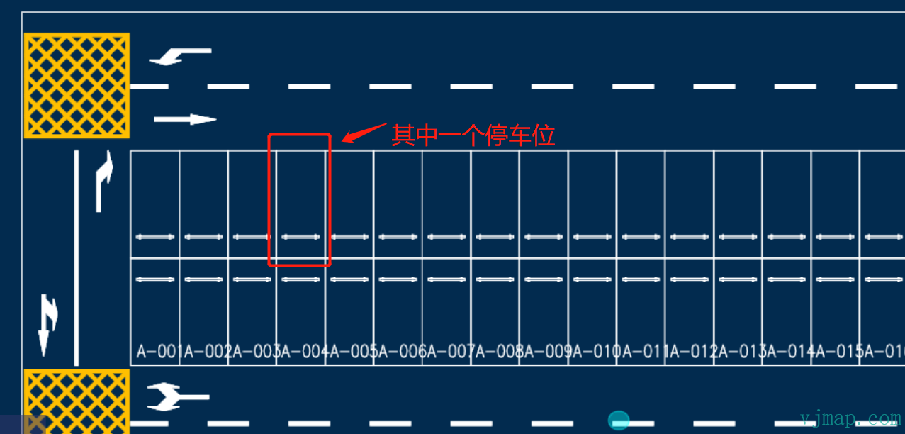
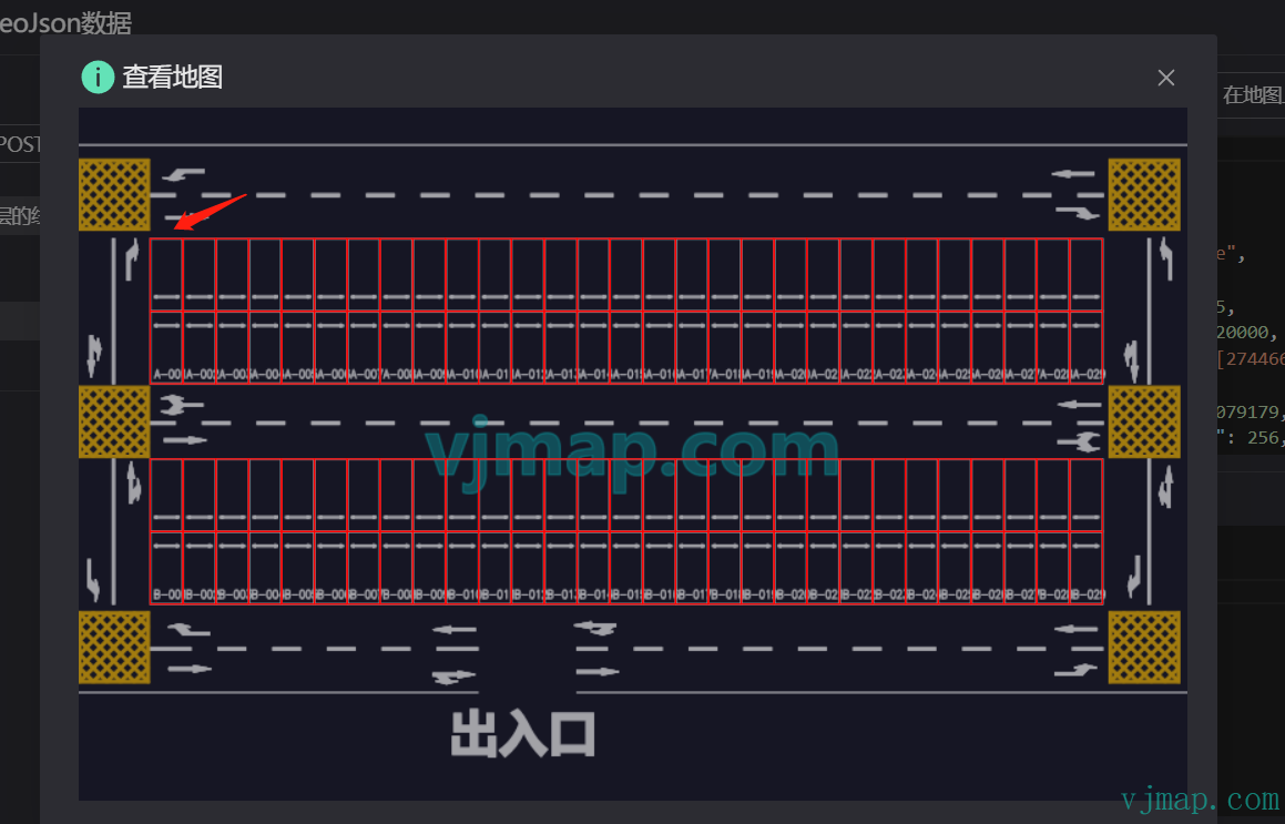
Using a parking lot CAD drawing as an example, how do we automatically recognize all parking spaces and obtain each space’s position and total count?
Typical recognition methods and flow:
Observe the CAD drawing: Inspect the drawing for shapes or symbols that may represent parking spaces, such as specific icons or markers. In this example, each parking space is a rectangle.
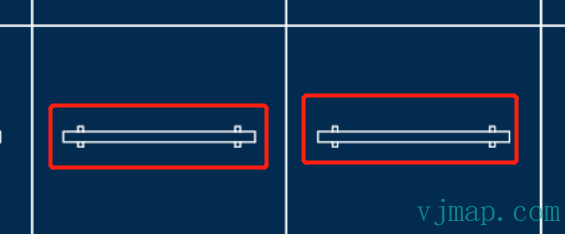
Check legends and annotations: CAD drawings often include legends or annotations explaining elements. Check whether they describe what to recognize. Here, each rectangle contains a parking line symbol.
Use CAD selection and query: Use CAD selection and query tools to select specific objects and view their properties. Use these tools on likely parking space objects to inspect attributes.
Check layers and structure: CAD drawings use layers to organize elements. Review the layer list for layers related to parking spaces and inspect them as needed.
Follow CAD standards and conventions: CAD drawings often follow standards and conventions, including specific symbols and representations for what you want to recognize.
For drawings that cannot be recognized by geometry alone, image recognition can be used:
Image processing and pattern recognition: Use techniques such as edge detection, contour extraction, and shape recognition to analyze CAD images. Computer vision libraries like OpenCV can be used.
Machine learning and deep learning: Train models to automatically recognize objects in CAD images. This involves using labeled CAD images as training data and training classifiers or CNNs. After training, new images can be fed to the model for prediction.
Using the parking lot CAD drawing above, we can recognize all parking spaces as follows:
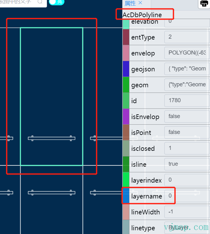
(1) By observation, all parking spaces are on layer "0" and are polylines ("AcDbPolyline")
(2) Query all polylines on layer "0" via CAD data query. Result:
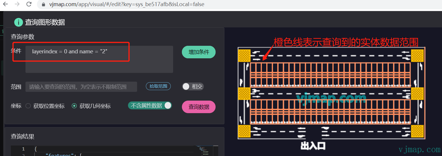
(3) The query returns all parking spaces, but also unwanted data (parking lines between spaces). Filter the results to keep only rectangular polylines (five points).
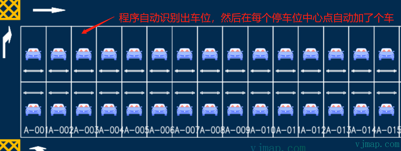
(4) All parking spaces are identified. We can get the center of each space, add a car symbol, and view the result:
Demo and video tutorial:
https://vjmap.com/app/visual/#/edit?key=sys_be517afb&isLocal=false (opens new window)
VJMap Visualization: Parking Lot Path Planning (opens new window) https://www.bilibili.com/video/BV1oX4y1r7L3/ (opens new window)
# Frontend CAD Recognition Methods Summary
# Method 1: Recognition by CAD Attribute Data
Use case: Data is regular; objects can be identified directly from attributes such as entity layer, color, entity type, area, hatch symbol, or same block.
For the parking lot example, parking spaces have the same area:
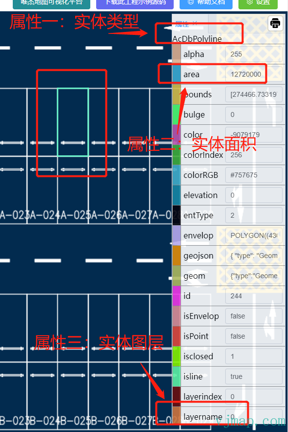
We can query directly with entity type = polyline, entity layer = "0", and entity area = 12720000 to get all parking spaces.
# Method 2: Recognition by CAD Attributes and Business Rules
Use case: When attributes alone are not enough, if related recognizable objects exist on the drawing, first recognize those, then apply business rules to identify the target objects.
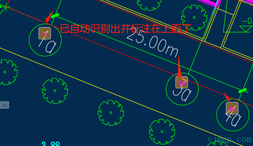
For example, to recognize all labels inside the circles:
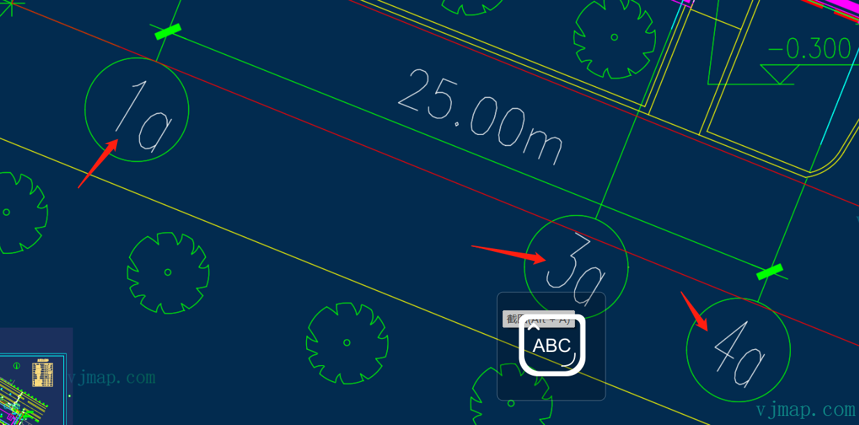
Querying all text yields many irrelevant labels. In practice, the desired labels are inside circles. So we first query all circles of the same size to get their centers and radii, then find all text inside each circle. Result:
Online demo and source: https://vjmap.com/demo/#/demo/map/service/22findtextbyrules (opens new window)
# Method 3: Recognition by Business Logic
Use case: For complex scenarios, implement custom business logic.
Example: automatically splitting a CAD drawing into multiple sheets and exporting submaps or images. This requires logic to find all submaps.
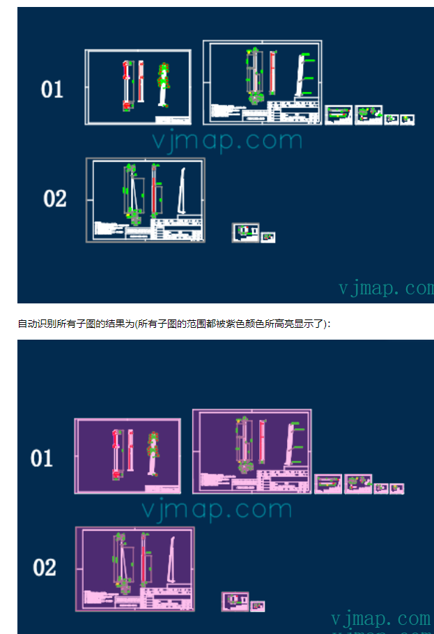
Auto-split algorithm principle:
Submaps are characterized by an outer drawing border. Finding all borders lets us split submaps by position. The outermost border is a rectangle that is not contained by any other rectangle.
(1) Traverse all rectangles and collect their extents
(2) Rectangles may be formed by four lines; collect all horizontal and vertical lines and check if they form rectangles
(3) For each rectangle, if it is not contained by another, treat it as a submap border.
See the blog post for details:
Online demo and source: https://vjmap.com/demo/#/demo/map/service/22findsubmapsplit (opens new window)
# Method 4: Recognition by Image Similarity
Use case: When geometry queries are not feasible, use image similarity for recognition.
Image similarity algorithms compare and measure similarity between images. Common algorithms include:
Perceptual Hashing: Compute a hash of the image, convert to a fixed-length binary string, and compare hashes to assess similarity.
Structural Similarity (SSIM): Based on human perception, compares structure, texture, and brightness to produce a similarity score.
Average Hashing: Resize the image to a fixed low resolution, compute average pixel value, compare each pixel to the average to generate a binary string, and compare strings.
Euclidean Distance: Compute Euclidean distance between image pixels. Smaller distance means more similar.
Cosine Similarity: Compute cosine of the angle between image vectors. Larger cosine means more similar.
Normalized Cross-Correlation: Compute cross-correlation between images. Higher correlation means more similar.
Typical flow:
(1) Convert geometry to image data via the WMS service
(2) Apply similarity comparison on the image data
(3) Convert pixel coordinates of matches back to geometry coordinates for display
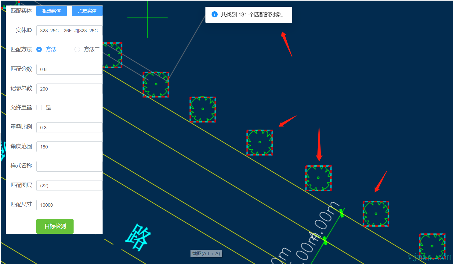
Example:
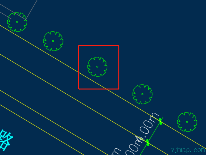
If the symbol is a block, we can use block identity for recognition. If it is drawn inconsistently and not a single block, attribute-based recognition is difficult. In that case, image recognition can be used. Result:
Online demo and source: https://vjmap.com/demo/#/demo/map/service/32mapmatchobject (opens new window)
# Method 5: Recognition by AI / Deep Learning
Use case: For complex objects with varying size, rotation, and scale, train a model and use AI for recognition.
The process is similar to Method 4: convert geometry to image data via the WMS service, run the image through a deep learning framework for object detection, and use the resulting coordinates for display.
Because the deep learning framework is not bundled, customers need to implement it themselves. No example is provided here.
# Summary
Automatic recognition and extraction of CAD drawing information is a complex task involving CAD parsing, pattern discovery, business understanding, image processing, and pattern recognition. You may need to combine multiple techniques and adapt them to your specific case.