threejs 几何体
threejs 几何体
原文地址 https://juejin.cn/post/7103057741547044900 原文地址 https://juejin.cn/post/7103058968595038244
课件地址: https://github.com/buglas/threejs-lesson
内置几何体
three.js 的内置几何体大致可分成以下几类:
- 二维几何体
- PlaneGeometry 矩形平面
- CircleGeometry 圆形平面
- RingGeometry 圆环平面
- ShapeGeometry 二维图形
- 三维几何体
- BoxGeometry 立方体
- TetrahedronGeometry 四面体
- OctahedronGeometry 八面体
- DodecahedronGeometry 十二面体
- IcosahedronGeometry 二十面体
- PolyhedronGeometry 多面体
- SphereGeometry 球体
- ConeGeometry 圆锥
- CylinderGeometry 圆柱
- TorusGeometry 三维圆环
- TorusKnotGeometry 扭结
- 路径合成几何体
- TubeGeometry 管道
- LatheGeometry 车削
- ExtrudeGeometry 挤压
- 线性几何体
- WireframeGeometry 网格几何体
- EdgesGeometry 边缘几何体
接下来,咱们详细说一下其绘制方法。
1-1-二维几何体
PlaneGeometry 矩形平面
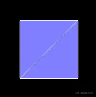
PlaneGeometry(width : Float, height : Float, widthSegments : Integer, heightSegments : Integer)
- width — 平面沿着X轴的宽度。默认值是1。
- height — 平面沿着Y轴的高度。默认值是1。
- widthSegments — (可选)平面的宽度分段数,默认值是1。
- heightSegments — (可选)平面的高度分段数,默认值是1。
代码实例:
1.先参照上一篇的项目架构一个一个react+ts 项目,详情参见源码。
2.建立一个Stage对象,把渲染器、场景、相机、轨道控制器和响应式布局都封装进去。这样在写例子的时候会比较方便、整洁。
- src/component/Stage.ts
import { PerspectiveCamera, Scene, WebGLRenderer } from "three";
import { OrbitControls } from "three/examples/jsm/controls/OrbitControls";

export default class Stage {
  // 渲染器
  renderer: WebGLRenderer;
  // 场景
  scene: Scene;
  // 相机
  camera: PerspectiveCamera;
  // 轨道控制器
  controls: OrbitControls;
  // 渲染之前
  beforeRender = (time: number = 0) => {};

  // 初始化场景
  constructor(x: number = 0, y: number = 0, z: number = 12) {
    this.scene = new Scene();
    this.renderer = new WebGLRenderer({ antialias: true });
    const { clientWidth, clientHeight } = this.renderer.domElement;
    this.renderer.setSize(clientWidth * devicePixelRatio, clientHeight * devicePixelRatio, false);
    this.camera = new PerspectiveCamera(45, clientWidth / clientHeight, 0.1, 1000);
    this.camera.position.set(x, y, z);
    this.camera.lookAt(0, 0, 0);
    this.controls = new OrbitControls(this.camera, this.renderer.domElement);
  }

  // 响应式布局
  responsive() {
    const { renderer, camera } = this;
    if (this.resizeRendererToDisplaySize(renderer)) {
      const { clientWidth, clientHeight } = renderer.domElement;
      camera.aspect = clientWidth / clientHeight;
      camera.updateProjectionMatrix();
    }
  }

  // 重置渲染尺寸
  resizeRendererToDisplaySize(renderer: WebGLRenderer): boolean {
    const { width, height, clientWidth, clientHeight } = renderer.domElement;
    const [w, h] = [clientWidth * devicePixelRatio, clientHeight * devicePixelRatio];
    const needResize = width !== w || height !== h;
    if (needResize) {
      renderer.setSize(w, h, false);
    }
    return needResize;
  }

  // 连续渲染
  animate(time = 0) {
    this.responsive();
    this.beforeRender(time);
    this.renderer.render(this.scene, this.camera);
    requestAnimationFrame((time) => {
      this.animate(time);
    });
  }
}
3.绘制矩形平面。
- src/component/Plane.ts
import React, { useRef, useEffect } from "react";
import {
  Mesh,
  MeshBasicMaterial,
  MeshNormalMaterial,
  PlaneGeometry,
} from "three";
import Stage from "../component/Stage";
import "./fullScreen.css";

const stage = new Stage();
const { scene, renderer } = stage;

const geometry = new PlaneGeometry();

{
  const material = new MeshNormalMaterial({
    polygonOffset: true,
    polygonOffsetFactor: 1,
    polygonOffsetUnits: 1,
  });
  const mesh = new Mesh(geometry, material);
  scene.add(mesh);
}
{
  const material = new MeshBasicMaterial({
    wireframe: true,
  });
  const mesh = new Mesh(geometry, material);
  scene.add(mesh);
}

const Plane: React.FC = (): JSX.Element => {
  const divRef = useRef<HTMLDivElement>(null);
  useEffect(() => {
    const { current } = divRef;
    if (current) {
      current.innerHTML = "";
      current.append(renderer.domElement);
      stage.animate();
    }
  }, []);
  return <div ref={divRef} className="canvasWrapper"></div>;
};

export default Plane;
CircleGeometry 圆形平面
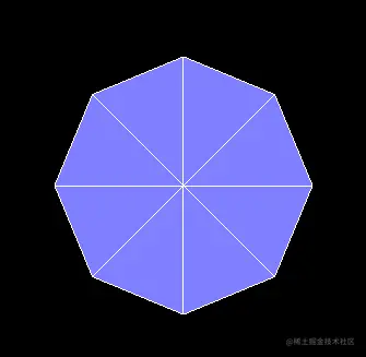
CircleGeometry(radius : Float, segments : Integer, thetaStart : Float, thetaLength : Float)
- radius — 圆形的半径,默认值为1
- segments — 分段(三角面)的数量,最小值为3,默认值为8。
- thetaStart — 第一个分段的起始角度,默认为0。(three o'clock position)
- thetaLength — 圆形扇区的中心角,通常被称为“θ”(西塔)。默认值是2*Pi,这使其成为一个完整的圆。
RingGeometry 圆环平面
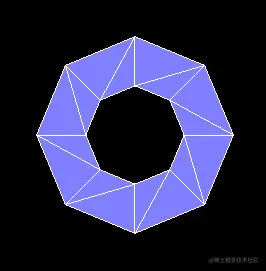
RingGeometry(innerRadius : Float, outerRadius : Float, thetaSegments : Integer, phiSegments : Integer, thetaStart : Float, thetaLength : Float)
- innerRadius — 内部半径,默认值为0.5。
- outerRadius — 外部半径,默认值为1。
- thetaSegments — 圆环的分段数。这个值越大,圆环就越圆。最小值为3,默认值为8。
- phiSegments — 最小值为1,默认值为8。
- thetaStart — 起始角度,默认值为0。
- thetaLength — 圆心角,默认值为Math.PI * 2。
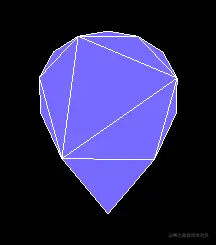
ShapeGeometry 二维图形
ShapeGeometry(shapes : Array, curveSegments : Integer)
- shapes — 一个单独的shape,或者一个包含形状的Array。
- curveSegments - Integer - 每一个形状的分段数,默认值为12。
代码示例:
const shape = new Shape();
shape.moveTo(0, 0);
shape.bezierCurveTo(1, 1, -1, 1, 0, 0);
const geometry = new ShapeGeometry(shape);
效果如下:
1-2-三维几何体
BoxGeometry 立方体
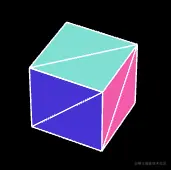
BoxGeometry(width : Float, height : Float, depth : Float, widthSegments : Integer, heightSegments : Integer, depthSegments : Integer)
- width — X轴上面的宽度,默认值为1。
- height — Y轴上面的高度,默认值为1。
- depth — Z轴上面的深度,默认值为1。
- widthSegments — (可选)宽度的分段数,默认值是1。
- heightSegments — (可选)高度的分段数,默认值是1。
- depthSegments — (可选)深度的分段数,默认值是1。
TetrahedronGeometry 四面体
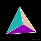
TetrahedronGeometry(radius : Float, detail : Integer)
- radius — 四面体的半径,默认值为1。
- detail — 默认值为0。将这个值设为一个大于0的数将会为它增加一些顶点,使其不再是一个四面体。
OctahedronGeometry 八面体
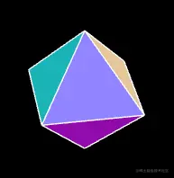
OctahedronGeometry(radius : Float, detail : Integer)
- radius — 八面体的半径,默认值为1。
- detail — 默认值为0,将这个值设为一个大于0的数将会为它增加一些顶点,使其不再是一个八面体。
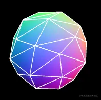
DodecahedronGeometry 十二面体
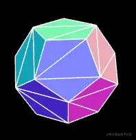
DodecahedronGeometry(radius : Float, detail : Integer)
- radius — 十二面体的半径,默认值为1。
- detail — 默认值为0。将这个值设为一个大于0的数将会为它增加一些顶点,使其不再是一个十二面体。
IcosahedronGeometry 二十面体
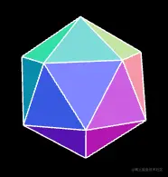
IcosahedronGeometry(radius : Float, detail : Integer)
- radius — 二十面体的半径,默认为1。
- detail — 默认值为0。将这个值设为一个大于0的数将会为它增加一些顶点,使其不再是一个二十面体。当这个值大于1的时候,实际上它将变成一个球体。
PolyhedronGeometry 多面体
PolyhedronGeometry(vertices : Array, indices : Array, radius : Float, detail : Integer
- vertices — 一个顶点Array(数组):[1,1,1, -1,-1,-1, ... ]。
- indices — 一个构成面的索引Array(数组), [0,1,2, 2,3,0, ... ]。
- radius — Float - 最终形状的半径。
- detail — Integer - 将对这个几何体细分多少个级别。细节越多,形状就越平滑。
代码示例:
const geometry = new PolyhedronGeometry(
  [-1, -1, -1, 1, -1, -1, 1, 1, -1, -1, 1, -1, -1, -1, 1, 1, -1, 1, 1, 1, 1, -1, 1, 1],
  [2, 1, 0, 0, 3, 2, 0, 4, 7, 7, 3, 0, 0, 1, 5, 5, 4, 0, 1, 2, 6, 6, 5, 1, 2, 3, 7, 7, 6, 2, 4, 5, 6, 6, 7, 4],
  1,
  1
);
效果如下:
SphereGeometry 球体
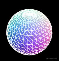
SphereGeometry(radius : Float, widthSegments : Integer, heightSegments : Integer, phiStart : Float, phiLength : Float, thetaStart : Float, thetaLength : Float)
- radius — 球体半径,默认为1。
- widthSegments — 水平分段数(沿着经线分段),最小值为3,默认值为32。
- heightSegments — 垂直分段数(沿着纬线分段),最小值为2,默认值为16。
- phiStart — 指定水平(经线)起始角度,默认值为0。。
- phiLength — 指定水平(经线)扫描角度的大小,默认值为 Math.PI * 2。
- thetaStart — 指定垂直(纬线)起始角度,默认值为0。
- thetaLength — 指定垂直(纬线)扫描角度大小,默认值为 Math.PI。
该几何体是通过扫描并计算围绕着Y轴(水平扫描)和X轴(垂直扫描)的顶点来创建的。
因此,我们可以通过为phiStart,phiLength,thetaStart和thetaLength属性对球体进行切片。
ConeGeometry 圆锥
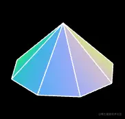
ConeGeometry(radius : Float, height : Float, radialSegments : Integer, heightSegments : Integer, openEnded : Boolean, thetaStart : Float, thetaLength : Float)
- radius — 圆锥底部的半径,默认值为1。
- height — 圆锥的高度,默认值为1。
- radialSegments — 圆锥侧面周围的分段数,默认为8。
- heightSegments — 圆锥侧面沿着其高度的分段数,默认值为1。
- openEnded — 一个Boolean值,指明该圆锥的底面是开放的还是封顶的。默认值为false,即其底面默认是封顶的。
- thetaStart — 第一个分段的起始角度,默认为0。(three o'clock position)
- thetaLength — 圆锥底面圆扇区的中心角,通常被称为“θ”(西塔)。默认值是2*Pi,这使其成为一个完整的圆锥。
CylinderGeometry 圆柱
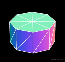
CylinderGeometry(radiusTop : Float, radiusBottom : Float, height : Float, radialSegments : Integer, heightSegments : Integer, openEnded : Boolean, thetaStart : Float, thetaLength : Float)
- radiusTop — 圆柱的顶部半径,默认值是1。
- radiusBottom — 圆柱的底部半径,默认值是1。
- height — 圆柱的高度,默认值是1。
- radialSegments — 圆柱侧面周围的分段数,默认为8。
- heightSegments — 圆柱侧面沿着其高度的分段数,默认值为1。
- openEnded — 一个Boolean值,表示该圆柱的底面和顶面是否开放。默认值为false,即闭合。
- thetaStart — 第一个分段的起始角度,默认为0。(three o'clock position)
- thetaLength — 圆柱底面圆扇区的中心角,通常被称为“θ”(西塔)。默认值是2*Pi,这使其成为一个完整的圆柱。
TorusGeometry 三维圆环
TorusGeometry(radius : Float, tube : Float, radialSegments : Integer, tubularSegments : Integer, arc : Float)
- radius - 环面的半径,从环面的中心到管道横截面的中心。默认值是1。
- tube — 管道的半径,默认值为0.4。
- radialSegments — 管道横截面的分段数,默认值为8。
- tubularSegments —圆环x的分段数,默认值为6。
- arc — 圆环的圆心角(单位是弧度),默认值为Math.PI * 2。
TorusKnotGeometry 扭结
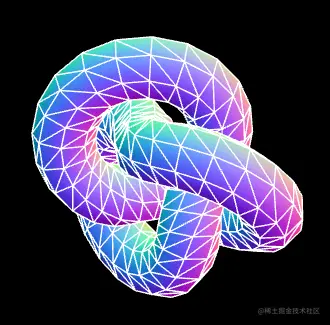
TorusKnotGeometry(radius : Float, tube : Float, tubularSegments : Integer, radialSegments : Integer, p : Integer, q : Integer)
radius - 圆环的半径,默认值为1。
tube — 管道的半径,默认值为0.4。
tubularSegments — 扭结线的分段数量,默认值为64。
radialSegments — 管道分段数量,默认值为8。
p — 这个值决定了几何体将绕着其旋转对称轴旋转多少次,默认值是2。
q — 这个值决定了几何体将绕着其内部圆环旋转多少次,默认值是3。
1-3-路径合成几何体
TubeGeometry 管道
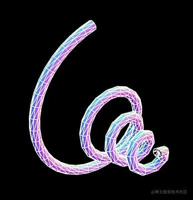
TubeGeometry(path : Curve, tubularSegments : Integer, radius : Float, radialSegments : Integer, closed : Boolean)
- path — Curve - 一个由基类Curve继承而来的3D路径。 Default is a quadratic bezier curve.
- tubularSegments — Integer - 组成这一管道的分段数,默认值为64。
- radius — Float - 管道的半径,默认值为1。
- radialSegments — Integer - 管道横截面的分段数目,默认值为8。
- closed — Boolean 管道的两端是否闭合,默认值为false。
代码示例:
1.自定义一个绘制曲线的curve对象
- src/component/CustomSinCurve
import { Curve, Vector3 } from "three";

export class CustomSinCurve extends Curve<Vector3> {
  getPoint(t: number): Vector3 {
    const a = t * 4 + 1;
    const ty = (a * Math.cos(t * Math.PI * 2 * 4)) / 8;
    const tz = (a * Math.sin(t * Math.PI * 2 * 4)) / 8;
    return new Vector3(t, ty, tz);
  }
}
2.建立管道几何体
const path = new CustomSinCurve();
const geometry = new TubeGeometry(path, 128, 0.05, 3, false);
LatheGeometry 车削
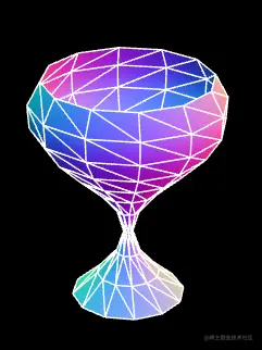
LatheGeometry(points : Array, segments : Integer, phiStart : Float, phiLength : Float)
- points — 一个Vector2对象数组。每个点的X坐标必须大于0。
- segments — 要生成的车削几何体圆周分段的数量,默认值是12。
- phiStart — 以弧度表示的起始角度,默认值为0。
- phiLength — 车削部分的弧度(0-2PI)范围,2PI将是一个完全闭合的、完整的车削几何体,小于2PI是部分的车削。默认值是2PI。
代码示例:
const points = [];
for (let i = 0; i < 1; i += 0.1) {
  const x = (Math.sin(i * Math.PI * 1.8 + 2.8) + 1.1) / 5;
  points.push(new Vector2(x, i));
}
const geometry = new LatheGeometry(points, 32, 0, Math.PI);
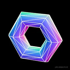
ExtrudeGeometry 挤压
ExtrudeGeometry(shapes : Array, options : Object)
- shapes — 形状或者一个包含形状的数组。
- options — 一个包含有下列参数的对象:
- steps — int,用于沿着挤出样条的深度细分的点的数量,默认值为1。
- depth — float,挤出的形状的深度,默认值为1。
- bevelEnabled — bool,对挤出的形状应用是否斜角,默认值为true。
- bevelThickness — float,设置原始形状上斜角的厚度。默认值为0.2。
- bevelSize — float。斜角与原始形状轮廓之间的延伸距离,默认值为bevelThickness-0.1。
- bevelOffset — float. Distance from the shape outline that the bevel starts. Default is 0.
- bevelSegments — int。斜角的分段层数,默认值为3。
- extrudePath — THREE.Curve对象。一条沿着被挤出形状的三维样条线。Bevels not supported for path extrusion.
- UVGenerator — Object。提供了UV生成器函数的对象。
该对象可以将一个二维形状挤成一个三维几何体。
当使用这个几何体创建Mesh的时候,如果你希望分别对它的表面和它挤出的侧面使用单独的材质,你可以使用一个材质数组。 第一个材质将用于其表面;第二个材质则将用于其挤压出的侧面。
代码示例:
const shape = new Shape();
shape.moveTo(0, 0);
shape.lineTo(0, 1);
shape.lineTo(1, 1);
shape.lineTo(1, 0);
shape.lineTo(0, 0);

const extrudeSettings = {
  steps: 1,
  depth: 1,
  bevelEnabled: true,
  bevelThickness: 0.2,
  bevelSize: 0.1,
  bevelOffset: 0,
  bevelSegments: 1,
};

const geometry = new ExtrudeGeometry(shape, extrudeSettings);
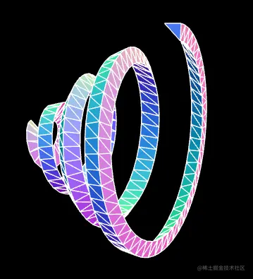
除此之外,我们还可以通过extrudePath 属性让一个二维图形沿curve 路径做挤压。
const shape = new Shape();
shape.moveTo(0, 0);
shape.lineTo(0.1, 0);
shape.lineTo(0.1, 0.1);
const path = new CustomSinCurve();
const geometry = new ExtrudeGeometry(shape, {
  steps: 128,
  extrudePath: path,
});
效果如下:
1-4-线性几何体
WireframeGeometry 网格几何体
WireframeGeometry( geometry : BufferGeometry )
- geometry — 任意几何体对象。
代码示例:
const line = new LineSegments(wireframe);
const mat = line.material as LineBasicMaterial;
mat.depthTest = false;
mat.opacity = 0.5;
mat.transparent = true;
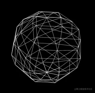
EdgesGeometry 边缘几何体
EdgesGeometry( geometry : BufferGeometry, thresholdAngle : Integer )
- geometry — 任何一个几何体对象。
- thresholdAngle — 仅当相邻面的法线之间的角度(单位为角度)超过这个值时,才会渲染边缘。默认值为1。
代码示例:
const geometry = new SphereGeometry(2, 8, 8);
const edges = new EdgesGeometry(geometry);
const line = new LineSegments(edges);
自定义几何体
1-基本概念
BufferGeometry 是所有three.js 内置几何体的基类,通过此基类可以自定义几何体。
BufferGeometry 具备以下重要属性:
- position 顶点位置
- index 顶点索引
- normal 法线
- uv 坐标
- color 顶点颜色
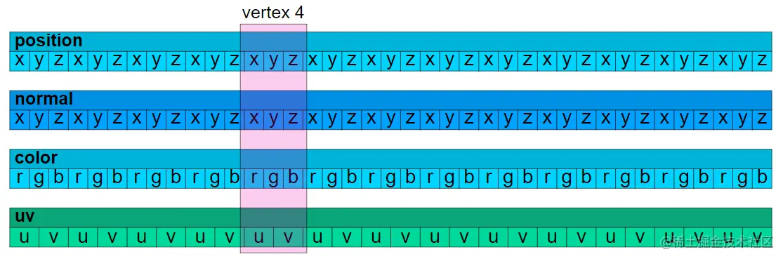
从上图可以看出,在顶点索引为4的地方,position 、normal 、uv 、color 是基于顶点一一对应的。
接下来咱们自己自定义一个几何体。
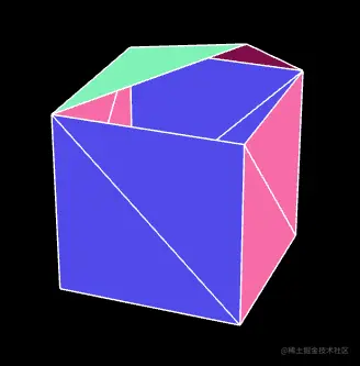
2-自定义立方体
1.在下面的vertices里,我们按照对立三角形的绘图方式,定义了立方体的6个面,共36个顶点。
const vertices = [
  // front
  { pos: [-1, -1,  1], norm: [ 0,  0,  1], uv: [0, 0], },
  { pos: [ 1, -1,  1], norm: [ 0,  0,  1], uv: [1, 0], },
  { pos: [-1,  1,  1], norm: [ 0,  0,  1], uv: [0, 1], },

  { pos: [-1,  1,  1], norm: [ 0,  0,  1], uv: [0, 1], },
  { pos: [ 1, -1,  1], norm: [ 0,  0,  1], uv: [1, 0], },
  { pos: [ 1,  1,  1], norm: [ 0,  0,  1], uv: [1, 1], },
  // right
  { pos: [ 1, -1,  1], norm: [ 1,  0,  0], uv: [0, 0], },
  { pos: [ 1, -1, -1], norm: [ 1,  0,  0], uv: [1, 0], },
  { pos: [ 1,  1,  1], norm: [ 1,  0,  0], uv: [0, 1], },

  { pos: [ 1,  1,  1], norm: [ 1,  0,  0], uv: [0, 1], },
  { pos: [ 1, -1, -1], norm: [ 1,  0,  0], uv: [1, 0], },
  { pos: [ 1,  1, -1], norm: [ 1,  0,  0], uv: [1, 1], },
  // back
  { pos: [ 1, -1, -1], norm: [ 0,  0, -1], uv: [0, 0], },
  { pos: [-1, -1, -1], norm: [ 0,  0, -1], uv: [1, 0], },
  { pos: [ 1,  1, -1], norm: [ 0,  0, -1], uv: [0, 1], },

  { pos: [ 1,  1, -1], norm: [ 0,  0, -1], uv: [0, 1], },
  { pos: [-1, -1, -1], norm: [ 0,  0, -1], uv: [1, 0], },
  { pos: [-1,  1, -1], norm: [ 0,  0, -1], uv: [1, 1], },
  // left
  { pos: [-1, -1, -1], norm: [-1,  0,  0], uv: [0, 0], },
  { pos: [-1, -1,  1], norm: [-1,  0,  0], uv: [1, 0], },
  { pos: [-1,  1, -1], norm: [-1,  0,  0], uv: [0, 1], },

  { pos: [-1,  1, -1], norm: [-1,  0,  0], uv: [0, 1], },
  { pos: [-1, -1,  1], norm: [-1,  0,  0], uv: [1, 0], },
  { pos: [-1,  1,  1], norm: [-1,  0,  0], uv: [1, 1], },
  // top
  { pos: [ 1,  1, -1], norm: [ 0,  1,  0], uv: [0, 0], },
  { pos: [-1,  1, -1], norm: [ 0,  1,  0], uv: [1, 0], },
  { pos: [ 1,  1,  1], norm: [ 0,  1,  0], uv: [0, 1], },

  { pos: [ 1,  1,  1], norm: [ 0,  1,  0], uv: [0, 1], },
  { pos: [-1,  1, -1], norm: [ 0,  1,  0], uv: [1, 0], },
  { pos: [-1,  1,  1], norm: [ 0,  1,  0], uv: [1, 1], },
  // bottom
  { pos: [ 1, -1,  1], norm: [ 0, -1,  0], uv: [0, 0], },
  { pos: [-1, -1,  1], norm: [ 0, -1,  0], uv: [1, 0], },
  { pos: [ 1, -1, -1], norm: [ 0, -1,  0], uv: [0, 1], },

  { pos: [ 1, -1, -1], norm: [ 0, -1,  0], uv: [0, 1], },
  { pos: [-1, -1,  1], norm: [ 0, -1,  0], uv: [1, 0], },
  { pos: [-1, -1, -1], norm: [ 0, -1,  0], uv: [1, 1], },
];
2.按照属性将这些顶点分成三组:
const positions = [];
const normals = [];
const uvs = [];
for (const vertex of vertices) {
  positions.push(...vertex.pos);
  normals.push(...vertex.norm);
  uvs.push(...vertex.uv);
}
3.基于positions、normals 和uvs 建立BufferAttribute 对象。
const geometry = new BufferGeometry();
const positionNumComponents = 3;
const normalNumComponents = 3;
const uvNumComponents = 2;
const positionAttr=new BufferAttribute(
  new Float32Array(positions),
  positionNumComponents
)
const normalAttr=new BufferAttribute(
  new Float32Array(normals),
  normalNumComponents
)
const uvAttr=new BufferAttribute(
  new Float32Array(uvs),
  uvNumComponents
)
BufferAttribute 对象就是对顶点着色器中Attribute 变量的管理,通过此对象可以存储顶点点位、顶点数量、矢量长度等,并可以对其进行矩阵变换、拷贝、读写等。
4.将BufferAttribute 对象添加到geometry 几何体中。
geometry.setAttribute('position',positionAttr);
geometry.setAttribute('normal',normalAttr);
geometry.setAttribute('uv',uvAttr);
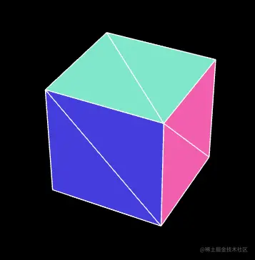
在setAttribute()中,'position'、'normal'、'uv'、' color ' 都是内置attribute 变量名,不能随便写。
当然如果我们想自定义attribute 变量名,那就可以随便写了,只要符合基本的命名规范就行。
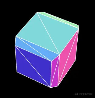
几何体形状如下:
自定义几何体的基本方法就是这样,接下来我们还可以使用顶点索引自定义几何体。
3-顶点索引
1.将vertices 设置为4*6=24 个点,一个面4个点。
const vertices = [
  // front
  { pos: [-1, -1,  1], norm: [ 0,  0,  1], uv: [0, 0], }, // 0
  { pos: [ 1, -1,  1], norm: [ 0,  0,  1], uv: [1, 0], }, // 1
  { pos: [-1,  1,  1], norm: [ 0,  0,  1], uv: [0, 1], }, // 2
  { pos: [ 1,  1,  1], norm: [ 0,  0,  1], uv: [1, 1], }, // 3
  // right
  { pos: [ 1, -1,  1], norm: [ 1,  0,  0], uv: [0, 0], }, // 4
  { pos: [ 1, -1, -1], norm: [ 1,  0,  0], uv: [1, 0], }, // 5
  { pos: [ 1,  1,  1], norm: [ 1,  0,  0], uv: [0, 1], }, // 6
  { pos: [ 1,  1, -1], norm: [ 1,  0,  0], uv: [1, 1], }, // 7
  // back
  { pos: [ 1, -1, -1], norm: [ 0,  0, -1], uv: [0, 0], }, // 8
  { pos: [-1, -1, -1], norm: [ 0,  0, -1], uv: [1, 0], }, // 9
  { pos: [ 1,  1, -1], norm: [ 0,  0, -1], uv: [0, 1], }, // 10
  { pos: [-1,  1, -1], norm: [ 0,  0, -1], uv: [1, 1], }, // 11
  // left
  { pos: [-1, -1, -1], norm: [-1,  0,  0], uv: [0, 0], }, // 12
  { pos: [-1, -1,  1], norm: [-1,  0,  0], uv: [1, 0], }, // 13
  { pos: [-1,  1, -1], norm: [-1,  0,  0], uv: [0, 1], }, // 14
  { pos: [-1,  1,  1], norm: [-1,  0,  0], uv: [1, 1], }, // 15
  // top
  { pos: [ 1,  1, -1], norm: [ 0,  1,  0], uv: [0, 0], }, // 16
  { pos: [-1,  1, -1], norm: [ 0,  1,  0], uv: [1, 0], }, // 17
  { pos: [ 1,  1,  1], norm: [ 0,  1,  0], uv: [0, 1], }, // 18
  { pos: [-1,  1,  1], norm: [ 0,  1,  0], uv: [1, 1], }, // 19
  // bottom
  { pos: [ 1, -1,  1], norm: [ 0, -1,  0], uv: [0, 0], }, // 20
  { pos: [-1, -1,  1], norm: [ 0, -1,  0], uv: [1, 0], }, // 21
  { pos: [ 1, -1, -1], norm: [ 0, -1,  0], uv: [0, 1], }, // 22
  { pos: [-1, -1, -1], norm: [ 0, -1,  0], uv: [1, 1], }, // 23
];
2.用BufferGeometry.setIndex() 方法设置顶点索引。
geometry.setIndex([
  // front
   0,  1,  2,   2,  1,  3,
  // right
   4,  5,  6,   6,  5,  7,
  // back
   8,  9, 10,  10,  9, 11,
  // left
  12, 13, 14,  14, 13, 15,
  // top
  16, 17, 18,  18, 17, 19,
  // bottom
  20, 21, 22,  22, 21, 23,
]);
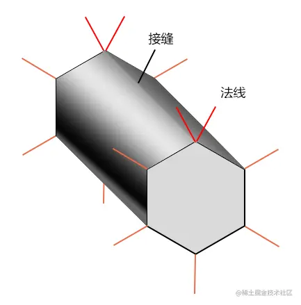
4-计算法线
BufferGeometry有一个自己根据现有顶点计算法线的方法computeVertexNormals()。
computeVertexNormals() 方法是按照逐顶点着色的方式计算法线的。
逐顶点着色的原理我们在webgl 的光里说过。
代码示例:
geometry.setAttribute("position", positionAttr);
// geometry.setAttribute("normal", normalAttr);
geometry.setAttribute("uv", uvAttr);
geometry.setIndex([0, 1, 2, 2, 1, 3, 4, 5, 6, 6, 5, 7, 8, 9, 10, 10, 9, 11, 12, 13, 14, 14, 13, 15, 16, 17, 18, 18, 17, 19, 20, 21, 22, 22, 21, 23]);
geometry.computeVertexNormals();
我们可以用VertexNormalsHelper 对象将一个Mesh对象的法线显示出来:
const cube = new Mesh(geometry, material);
const helper = new VertexNormalsHelper(cube);
scene.add(mesh, helper);
效果如下:
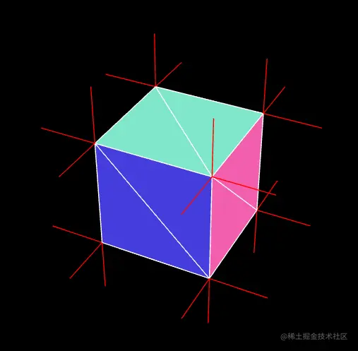
在用computeVertexNormals() 方法计算法线的时候,若在光滑的物体表面发现了明显的接缝线,那这可能就是由两排位置相同、法线不同的顶点引起的。
这需要我们自己根据模型特征调整法线,将这两排顶点的法线调成一样。
5-顶点数据的更新
当我们想要修改几何体的顶点数据的时候,可以直接通过BufferGeometry 对象下的BufferAttribute 修改。
举个例子:我要在一秒后,把上面自定义的几何体打开一个口子。
代码如下:
setTimeout(() => {
  positionAttr.setXYZ(18, 1, 2, 1);
  positionAttr.needsUpdate = true;
}, 1000);
接下来在渲染器执行render() 方法时,便会将最新的顶点数据传递给顶点着色器里的attribute 变量。
关于几何体的基础知识,咱们就说到这,接下来咱们做点好玩的东西,巩固咱们之前的所学。
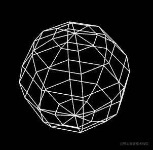
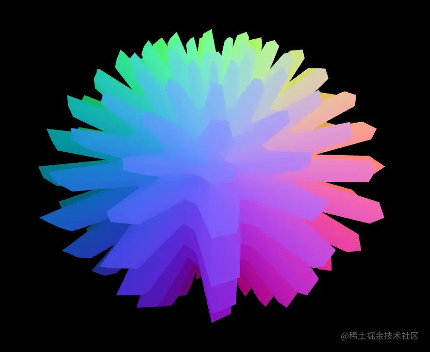
案例-自定义波浪球
下面这个绚丽的波浪球就是我们接下来要做的,我之后还会让它蠕动来。其中会制涉及的知识点有自定义几何体的封装、几何体顶点数据的读写、正弦函数动画等。
1.封装一个波浪球对象。
import {
    BufferGeometry,
    Vector3,
    Object3D,
    BufferAttribute,
    InterleavedBufferAttribute,
    Euler,
} from "three"
const pi2 = Math.PI * 2

export default class WaveBall extends BufferGeometry {
    // 分段数
    widthSegments: number
    heightSegments: number
    // 正弦参数y=Asin(ωx+φ)
    a: number = 0.7
    omega: number = 12

    constructor(widthSegments: number = 18, heightSegments: number = 12) {
        super()
        this.widthSegments = widthSegments
        this.heightSegments = heightSegments
        this.init()
    }
    init() {
        const { widthSegments, heightSegments } = this
        //网格线的数量
        const [width, height] = [widthSegments + 1, heightSegments + 1]
        //顶点数量
        const count = width * height
        //顶点点位
        const positions = new Float32Array(count * 3)
        //顶点索引
        const indices = []

        //根据经纬度计算顶点点位的方法
        const setPos = SetPos(positions)

        // 逐行列遍历
        for (let y = 0; y < height; ++y) {
            // 维度[-Math.PI/2,Math.PI/2]
            const lat = (y / heightSegments - 0.5) * Math.PI
            for (let x = 0; x < width; ++x) {
                // 经度[-Math.PI,Math.PI]
                const long = (x / widthSegments - 0.5) * Math.PI * 2
                // 设置顶点点位
                setPos(lat, long)
                // 设置顶点索引
                if (y && x) {
                    // 一个矩形格子的左上lt、右上rt、左下lb、右下rb点
                    const lt = (y - 1) * width + (x - 1)
                    const rt = (y - 1) * width + x
                    const lb = y * width + (x - 1)
                    const rb = y * width + x
                    indices.push(lb, rb, lt, lt, rb, rt)
                }
            }
        }
        this.setAttribute("position", new BufferAttribute(positions, 3))
        this.setIndex(indices)
        this.computeVertexNormals()
    }
    //波浪
    wave(phi = 0) {
        const { widthSegments, heightSegments, a, omega } = this
        //网格线的数量
        const [width, height] = [widthSegments + 1, heightSegments + 1]
        // 顶点点位
        const posAttr = this.getAttribute("position")
        // 修改点位的方法
        const changePos = ChangePos(posAttr)
        // 一圈波浪线的总弧度
        const allAng = omega * pi2
        // 每个分段的弧度
        const yAng = allAng / heightSegments
        const xAng = allAng / widthSegments
        // 逐行列遍历
        for (let y = 0; y < height; ++y) {
            // y向起伏
            const r0 = Math.sin(y * yAng + phi)
            // 基于y值做起伏衰减
            const decay = a * 0.2 + a * (0.5 - Math.abs(y / heightSegments - 0.5))
            for (let x = 0; x < width; ++x) {
                // x向起伏
                const r1 = Math.sin(x * xAng + phi)
                // 基于半径修改顶点位置
                changePos((r0 + r1) * decay + 1)
                // changePos(r0 * r1 * decay + 1)
                // changePos(r1 * 0.1 + 1)
            }
        }
        // this.computeVertexNormals()
        // 顶点数据需要更新
        posAttr.needsUpdate = true
    }
}

// 基于半径修改顶点位置
function ChangePos(attr: BufferAttribute | InterleavedBufferAttribute) {
    let index = 0
    // 根据索引获取顶点
    const getXYZ = GetXYZ(attr)
    return function (r: number) {
        const p = getXYZ(index)
        p.setLength(r)
        // 设置指定索引位的顶点的x、y、z值
        attr.setXYZ(index, ...p.toArray())
        index += 1
    }
}

// 根据索引获取顶点
function GetXYZ(attr: BufferAttribute | InterleavedBufferAttribute) {
    return function (ind: number) {
        return new Vector3(attr.getX(ind), attr.getY(ind), attr.getZ(ind))
    }
}

// 基于经纬度计算顶点点位
function SetPos(positions: Float32Array) {
    let posNdx = 0
    //根据经纬度获取点位
    // const getPoint = GetPoint()
    return function (lat: number, long: number) {
        const pos = getPoint(lat, long)
        positions.set(pos, posNdx)
        posNdx += 3
        return pos
    }
}
// 获取顶点位
function GetPoint() {
    //经度辅助对象
    const longHelper = new Object3D()
    //维度辅助对象
    const latHelper = new Object3D()
    // 顶点辅助对象
    const pointHelper = new Object3D()
    //构建层级关系
    longHelper.add(latHelper)
    latHelper.add(pointHelper)
    pointHelper.position.z = 1
    //暂存顶点
    const temp = new Vector3()
    return function (lat: number, long: number) {
        // 旋转经、纬度辅助对象
        longHelper.rotation.y = long
        latHelper.rotation.x = lat
        // 返回longHelper的世界坐标位
        return pointHelper.getWorldPosition(temp).toArray()
    }
}
// 欧拉
function getPoint(lat: number, long: number) {
    const euler = new Euler(lat, long, 0, "YXZ")
    const p = new Vector3(0, 0, 1)
    p.applyEuler(euler)
    return p.toArray()
}
2.将波浪球实例化
const geometry = new WaveBall(48, 48);
geometry.wave();
3.之后我们也可以在连续渲染方法里将时间传递到geometry.wave()里,作为波浪的偏移值。
stage.beforeRender = (time = 0) => {
    geometry.wave(time * 0.002)
}