# Coordinate Transformation
# Why Coordinate Transformation Is Needed
The CAD 2D graphics world coordinate system is a Cartesian coordinate system, and the extent of a drawing refers to the range occupied by the drawn graphics.
For example, if a user draws a line at coordinates [1000,1000] and [2000,2000], the extent of the drawing [top-left x, bottom-left y, top-right x, bottom-right y] is [1000,1000,2000,2000].
However, sometimes users draw with geodetic coordinates, which can be very large. For instance, drawing a line at coordinates [600000000,30000000] and [620000000,50000000] results in an extent of [600000000,30000000,700000000,70000000].
Meanwhile, when developing with internet-based maps, longitude and latitude values are relatively small.
To address the rendering of large coordinates and to unify coordinates between internet basemaps and CAD basemaps, our rendering layer uses longitude/latitude for rendering. During drawing, actual coordinates must be converted to longitude/latitude. The longitude range is (-180,180) and the latitude range is (-85,85).
# Coordinate Transformation Relationships
| Name | Description |
|---|---|
| Geometric coordinates | Actual coordinates in the CAD drawing |
| Longitude/Latitude coordinates | Longitude/latitude coordinates (must be converted to longitude/latitude for rendering) |
| Mercator coordinates | Projection coordinates |
# When the Basemap Is a CAD Drawing Coordinate System
The transformation relationship is shown below:
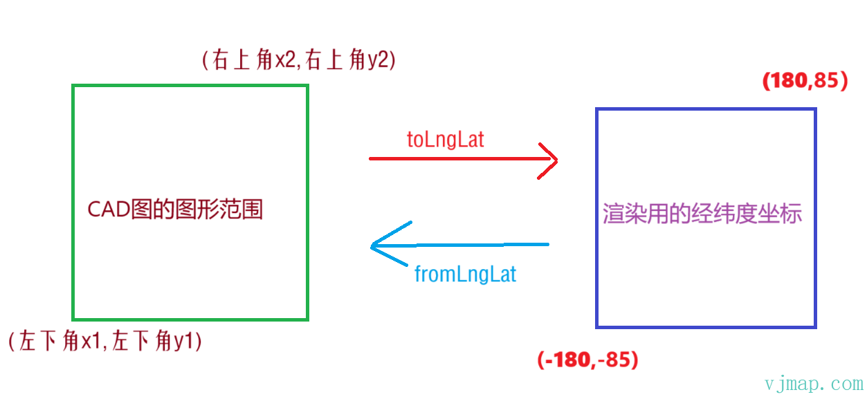
By calling toLngLat, CAD coordinates are converted to longitude/latitude coordinates used for rendering. For example, [bottom-left x1, bottom-left y1 of CAD extent] is converted to longitude/latitude [-180,-85].
So the longitude/latitude produced here is only for underlying rendering; it is not the actual longitude/latitude used in internet maps. These are two different concepts.
# When the Basemap Is an Internet Map (e.g., Tianditu)
The transformation relationship is shown below:
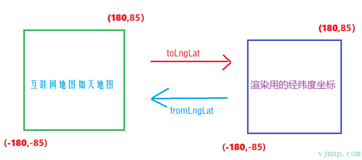
In this case, the extent of the internet map matches the longitude/latitude range used for rendering exactly. So the longitude/latitude produced here is the actual longitude/latitude used in internet maps. These are the same concept.
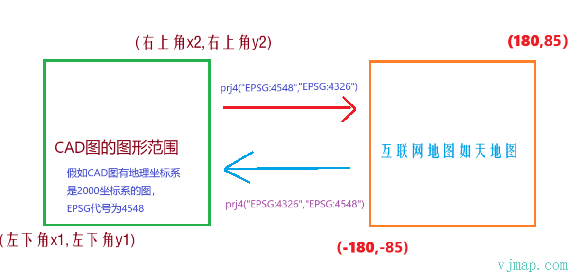
# Converting CAD Drawings with Geographic Coordinate Systems to Internet Map Longitude/Latitude
When a CAD drawing has a geographic coordinate system (e.g., CGCS2000) and needs to be converted to internet map longitude/latitude, a third-party coordinate conversion library such as proj4 is required. The conversion principle is shown below:
# Converting Between UCS and WCS Coordinates in CAD Drawings
When a drawing is opened in the cloud management platform, if the ucsorg value in the right-side property panel is non-zero, it indicates UCS is present. You can also use the map's hasUcs method to check for UCS coordinates.
VJMap returns CAD WCS coordinates.
Use map.wcsToUcs to convert WCS coordinates to UCS coordinates.
Use map.ucsToWcs to convert UCS coordinates to WCS coordinates.
# Summary
Summary 1
The longitude/latitude coordinates used for VJMap rendering are only true longitude/latitude when the basemap is an internet basemap (e.g., Tianditu, Amap).
When the basemap is CAD, the longitude/latitude values are only used for underlying rendering and have no real geographic meaning. They exist to handle large coordinate rendering and to unify coordinates between internet and CAD basemaps.
If the CAD basemap has a real geographic coordinate system (e.g., Beijing 54, Xi'an 80, CGCS2000) and needs to be converted to WGS84 longitude/latitude, you can use the SDK's vjmap.transform.convert method or a third-party library such as proj4. See the Internet Map demo for details,
or use four-parameter transformation to convert between different coordinate systems How to overlay data from another coordinate system onto the current CAD drawing (opens new window)
Summary 2
If the map is associated with a projection object map.attach(svc, prj) then
map.toLngLat is equivalent to prj.toLngLat
map.fromLngLat is equivalent to prj.fromLngLat
To convert CAD geometric coordinates to underlying rendering longitude/latitude, always call toLngLat (anything related to underlying drawing must use toLngLat to convert to longitude/latitude).
To convert underlying rendering longitude/latitude to CAD geometric coordinates, always call fromLngLat (to obtain actual geometric coordinates on the CAD drawing, use fromLngLat to convert to CAD coordinates).
Summary 3
Because the conversion from CAD coordinates to rendering longitude/latitude is nonlinear, use CAD geometric coordinates for geometric calculations such as intersection and interpolation. Convert to longitude/latitude coordinates only when rendering.
Summary 4
Because the conversion from CAD coordinates to rendering longitude/latitude depends on the current drawing extent of the CAD map, changes in the drawing extent will change the resulting longitude/latitude values. Therefore, when saving coordinates to the backend for later loading and display, always save CAD coordinates, not longitude/latitude. If the CAD drawing is updated and the drawing extent changes, loading longitude/latitude coordinates will no longer align with the drawing. Loading CAD coordinates will always align correctly.
For example, the Custom Highlight Region (opens new window) demo
When clicking save data, the rendering longitude/latitude of the drawing object is obtained, then converted to CAD geometric coordinates via map.fromLngLat before saving to the backend
// Saving data to backend
// Get rendering longitude/latitude of the drawing object
let lngLatJson = draw.getAll();
// Convert rendering longitude/latitude to CAD geometric coordinates
let cadJson = map.fromLngLat(lngLatJson);
2
3
4
5
When loading backend data for display on the map, use map.toLngLat to convert CAD geometric coordinates to rendering longitude/latitude for the drawing object.
// Load backend data for display on frontend
let cadJson = {......}; // CAD geometric coordinates from backend
// Convert CAD geometric coordinates to rendering longitude/latitude
let lngLatJson = map.toLngLat(cadJson);
// Set drawing object coordinates
draw.set(lngLatJson)
2
3
4
5
6
# How to Perform Coordinate Transformation on CAD Drawings
- Obtain the four-parameter transformation
Pick
three or morecorresponding point pairs on the CAD drawing (common points should be distributed around the drawing)
let pts = [
    {
        cadX: 1, // Coordinate X of point one on the CAD drawing
        cadY: 1, // Coordinate Y of point one on the CAD drawing
        destX: 101, // Coordinate x of point one on the target drawing
        destY: 101, // Coordinate y of point one on the target drawing
    },
    {
        cadX: 1, // Coordinate X of point two on the CAD drawing
        cadY: 5, // Coordinate Y of point two on the CAD drawing
        destX: 101, // Coordinate x of point two on the target drawing
        destY: 105, // Coordinate y of point two on the target drawing
    },
    {
        cadX: 5, // Coordinate X of point three on the CAD drawing
        cadY: 5, // Coordinate Y of point two on the CAD drawing
        destX: 105, // Coordinate x of point three on the target drawing
        destY: 105, // Coordinate y of point three on the target drawing
    }
]
let cadPoints = [];
let destPoints = [];
for(let n = 0; n < pts.length; n++) {
    cadPoints.push(vjmap.geoPoint([pts[n].cadX, pts[n].cadY]))
    destPoints.push(vjmap.geoPoint([pts[n].destX, pts[n].destY]))
}

// Calculate four parameters from coordinate pairs
let fourparam = vjmap.coordTransfromGetFourParamter(cadPoints, destPoints, false);
console.log([fourparam.dx, fourparam.dy, fourparam.scale, fourparam.rotate])

// Calculate error
for(let i = 0; i< cadPoints.length; i++) {
    const destPt = vjmap.coordTransfromByFourParamter(cadPoints[i], fourparam);
    console.log("Original point: " + cadPoints[i], "Result: " + destPt, "Error: " + destPoints[i].distanceTo(destPt))
}
2
3
4
5
6
7
8
9
10
11
12
13
14
15
16
17
18
19
20
21
22
23
24
25
26
27
28
29
30
31
32
33
34
35
36
For example, to convert a UCS drawing to WCS coordinates
Use the following code to automatically obtain the four parameters for WCS to UCS conversion:
let cadPoints = [];
let destPoints = []
// Get four points of the map extent to compute corresponding UCS coordinates as common points
let mapExtent = map.getMapExtent()
let pts = mapExtent.toPointArray()
for (let n = 0; n < pts.length; n++) {
    let wcs = vjmap.geoPoint(pts[n]);
    let ucs = map.wcsToUcs(wcs);
    cadPoints.push(wcs)
    destPoints.push(ucs);
}
// Calculate four parameters from coordinate pairs
let fourparam = vjmap.coordTransfromGetFourParamter(cadPoints, destPoints, false);
console.log([fourparam.dx, fourparam.dy, fourparam.scale, fourparam.rotate])
2
3
4
5
6
7
8
9
10
11
12
13
14
Open this drawing in the cloud management platform and click
Online Process GraphicsunderMore FeaturesIn
Online Process Graphics, enter the four parametersfourparam.dx, fourparam.dy, fourparam.scale, fourparam.rotateinDirect Four-Parameter FormatClick OK and choose to create a new drawing.
# Coordinate Control
CAD as basemap coordinate system
Internet map as basemap coordinate system